software and hardware fundamentals
note that this is only an early reference that I initially created for mysELF. I decided to publish it for those, who want to have an overview of the fundamentals. if you spot any mistakes or if you think something should be added, please reach me on discord (bitfriends). I used some pictures from other people because this was only a reference for me. the people who created the pictures are amazing and should feel honored :)
table of contents
- computer components are their functionalities
– the CPU
– the MMU
– the RAM
– the bus - the x86(-64) architecture
– overview
– data
– segmentation
– CPU registers
– call stack
– privilege/protection rings - Linux operating system and kernel
– overview
– the kernel
– syscalls and interrupts
– modern exploit mitigations (kernel space)
– Linux calling convention - ELF file format (Linux)
– overview
– structure
– how an ELF file is executed
– static vs dynamic binaries
– shared libraries
– modern exploit mitigations (userspace)
– the linker, the plt and the got - Windows operating system and kernel
– overview
– the kernel
– syscalls and interrupts
– modern exploit mitigations (kernel space)
– Windows calling convention - PE file format (Windows)
– overview
– structure
– modern exploit mitigations (userspace) - sources
computer components
CPU (central processing unit - assuming it has x86 architecture)
it is a little electronic device that executes instructions (machine code). the CPU can do logic, arithmetic, controlling and input/output operations which are specified by the machine code instructions. the CPU is divided into units, each of them associated with specific tasks. the machine code is located in the main memory (RAM) and secondary memory. the CPU also has registers that are like global variables. they are locations in the CPU that can be used to store small amounts of data. the size of the registers depends on the processor architecture and generation. the CPU cache is used by the CPU to save resources. it is closer to the CPU than the main memory and it stores copied data which is more frequently used. most CPUs have a hierarchy of multiple cache levels, in most cases L1, L2, and L3. while every CPU core has its own L1 and L2 cache, the L3 cache is always shared between them. CPU cache is utilized for frequently-used data, to allow faster access.

RAM (random access memory) & virtual memory
the ram is our main memory. it is a device where machine code and other data are stored. if we have a process, its code and most other data are in memory. if we have multiple programs running, using physical memory alone would be inefficient and expensive. also, you don’t want your program to interact with the hardware directly. instead, it should think, that it has access to all available memory. mainly because of that reason, every process has its own memory (called virtual memory), while the process can’t access the virtual memory of another process. virtual memory is partially in the physical address space and some fragments are in inactive/secondary memory, which form a range of continuous addresses. address spaces that are more frequently used get more main memory than those that aren’t read or written that often. the operating system tries to effectively move less frequently used data into secondary memory, which is known as swapping. also, big parts of the kernel are mapped to each program’s virtual address space (not directly accessible). there is also data in the kernel which is process-specific. this data is not shared between processes, instead, each has its unique data.
MMU
the MMU is part of the CPU (CPU unit) and it’s a computer hardware unit having all memory references passed through itsELF, primarily performing the translation of virtual memory addresses to physical addresses. modern MMUs typically divide the virtual address space into pages (chunks of memory, typically 1KB). most MMUs use an in-memory table of items called a page table (which is stored in kernel space of a program’s virtual address space), containing one page table entry per page, to map virtual page numbers to physical page numbers in main memory. the MMU knows where the current page table of the process is because the address of it is stored in a CPU register. simply said, the MMU is responsible to translate virtual addresses to physical addresses. they also have a cache called translation lookaside buffer.

BUS
a bus is a communication system that transfers data between components inside a computer. an address bus is a bus that is used to specify a physical address. when a processor needs to read or write to a memory location, it specifies that memory location on the address bus with a physical address (data is sent on the data bus). just imagine the data bus like a highway that transfers data. the location of what to read or write is specified on the address bus.
the x86 architecture
overview
different CPUs may have different architectures. x86 is one of them. it was originally designed by intel. by today x86 and its extensions are still commonly used. the most popular example is x86-64 or amd64, an extension by AMD.
data
the x86 architecture is a CISC (Complex instruction set computer) architecture. unlike RISC (Reduced instruction set computer) architectures, CISC computers can execute several more specialized low-level operations, while RISC is a computer with a small, highly optimized set of instructions. data is stored in memory with little-endian order. the largest value for int, memory address, or register is 16-bit, 32-bit, or 64-bit, depending on the processor generation.
processor modes (8080 - x86-64)
processor modes are various ways how the processor creates an operating environment. the processor mode controls how the processor manages the system memory, the tasks that use it, registers, etc. I listed the most important ones, starting with older ones.
- real mode flat model (unreal mode)
– 16-bit architecture
– CPU can only access 64K at a time (due to 16-bit limitation)
– your program and its data must exist within a 64K block of memory
– segment registers are set to the beginning of the memory block by the OS. they won’t change as long as the program is running
– the data of your program isn’t really divided into segments
– it is using 16-bit addresses - real mode segmented model
– 16-bit architecture
– CPU can access 1MB (because of using segment selectors, see below)
– your program and its data can use the full 1MB of memory
– the programmer has to set the segment registers
– the data of your program is divided into segments
– it is using 20-bit addresses. you can access data withsegment:offset, having them stored in two different registers. you can also useoffsetonly, but you can’t access data that are at a memory location higher than0xffff. - protected mode
– 32-bit architecture
– CPU can access over 4GB
– your program is given a 4GB block of memory
– the segment registers are managed by the OS and cannot be changed. their new job is to locate the “flat” segment in virtual memory.
– 32-bit addresses are used - long mode - like protected mode, but everything is 64 bit wide and more memory can be accessed
for compatibility reasons and/or for certain low level operations, modern CPUs can switch into other (older) processor modes
memory segmentation
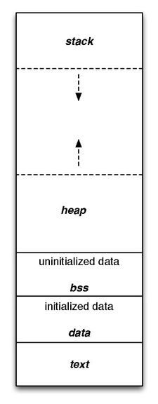
memory segmentation is an operating system memory management technique of division of a computer’s primary memory into segments or sections. talking of protected and long mode, you know that every program has its own virtual address space. inside that is its data and code. the data and code are split into segments (an area in virtual memory for computer use), which are sometimes divided again into sections that are for more specific use (later more). for example, there is the text segment, where your code is in. the data and bss segments are for data, to be more precise, the data is for initialized, and the bss is for uninitialized variables. the heap segment is also used for data. but it is dynamic memory, which means that you can request and release memory from the heap segment. last but not least there is the stack segment or only stack, which is also used to store data, especially local variables. it is like a real stack, where you can put something on top of it (called push-operation) and remove something from the top (called pop-operation). you cannot push or pop something from the bottom of the stack which doesn’t work in real life either. I will explain later when what is used. this is how it would look like:
CPU registers
the most important ones (user accessible):
| bits | stack-pointer | frame-pointer | general purpose / other |
|---|---|---|---|
| 16 | sp | bp | ax, bx, cx, dx, … |
| 32 | esp | ebp | eax, ebx, ecx, edx, edi, esi, … |
| 64 | rsp | rbp | rax, rbx, rcx, rdx, rdi, rsi, … |
| 128 | - | - | xmm0, xmm1, xmm2, … |
| 256 | - | - | ymm0, ymm1, ymm2, … |
| 512 | - | - | zmm0, zmm1, zmm2, … |
* some registers are only present on specific architectures
most registers are for general use, however, there is the register rbp/ebp/bp (frame/base pointer - points to the current stack frame), rsp/esp/sp (stack pointer - points on the top of the stack), and the rip/eip/ip (instruction pointer - points to the instruction which will be executed by the CPU). after the instruction was executed, the instruction pointer will be incremented to point to the next instruction, if no controlling/control transfer instruction was executed. more on the base pointer and the instruction pointer in the next chapter.
call stack
the call stack is an area on the stack for local variables and the return address of a function. these areas are called stackframes. the rbp register points to the current stack frame. after a call the return address is pushed onto the stack and it is jumped to the specified address. then the function sets up its stack frame, saves rbp, and does its actual job. after that, the stack pointer and the base pointer are restored, and the ret instruction is executed. it pops the previously-stored return address into rip and continues execution there.
CPU protection/privilege rings
computer operating systems provide different levels of access to resources. they are mechanisms to protect data and functionality from faults and malicious behavior. rings are arranged in a hierarchy from most privileged (most trusted, usually numbered zero) to least privileged (least trusted, usually with the highest ring number). on most operating systems, ring 0 is the level with the most privileges and interacts most directly with the physical hardware such as the CPU and memory (the kernel is in ring 0 of course). normal applications are usually in the least privileged ring (on Linux in ring 3). in this state, the hardware is pretty much locked up. that’s why there are syscalls and interrupts. with them you switch to ring 0 and changes to the hardware can be done.
the Linux OS and kernel
overview
Linux was released in 1991. it is a unix-like operating system. that means that it is not derived from unix, but it is similar. Linux itsELF is not an OS, instead, it’s a kernel. several Linux distributions are all based on the Linux kernel. the standard format for executables is ELF.
the Linux kernel
the kernel in general is like a program that has full control of the operating system. the kernel is a bridge between the hardware and software. after the bootloader (which is responsible to boot the system) the kernel is the first program loaded on startup. it handles the rest of startup as well as memory and input/output (I/O) requests from software, translating them into data-processing instructions for the CPU. Linux is a monolithic kernel, which means that the kernel not only interacts with the CPU and memory but also has device drivers and other kernel services running in kernel space only (read further for the definition of kernel space). they are best at communicating with hardware and performing several tasks simultaneously. it is for this reason that processes here react at a fast rate. the kernel manages the hardware with interrupts. if we talk about the virtual memory of a program, we divide it into user space and kernel space. in userspace, there is the program code, the data of the program and shared libraries, etc. and in kernel space is data of the kernel. in general, in user space are all the programs and libraries and in kernel space is the whole kernel and its drivers and modules. this applies to Windows too (at least NT based)
syscalls and interrupts
when the software or hardware wants to interface with the system, an interrupt is triggered (the hardware sends signals to the CPU through the bus, the software uses the int instruction), which interrupts the processor which does the same to the kernel. interrupts are used for implementing device drivers or transitions between protected modes of operation, such as system calls. the interrupt handler saves the current system state and runs the to the interrupt associated interrupt handling code. after that, the interrupt handler restores the state as it was before the interrupt. when another process requests a service from the kernel, the process has to do a system call. many different syscalls are doing different things. they are defined in the kernel and they do low-level operations. on 64-bit, they are triggered with a syscall instruction. before that, the syscall number and the arguments for the syscall are stored in specific registers. when a syscall instruction is executed, the value from the IA32_LSTAR register (prepared on kernel boot, only accessible in kernel space / ring zero) is moved into rip and jumped to that address (in kernel space). there the register which contains the syscall number is checked and it is jumped to the right syscall code (the address is in the syscall table). after the syscall is finished, you jump back to the instruction following the syscall instruction. its address was saved earlier in rcx. on 32-bit, you use interrupts to jump to the code in kernel space (interrupt handling code) which executes the syscalls (you use int 0x80). the addresses of the interrupt handlers are stored in the interrupt vector table. usually, a program does not use syscalls directly. instead, wrappers from the shared libraries are used. but there are also other kernel functions, which can’t be used by a normal application.
modern exploit mitigation features (kernelspace)
| kernel access layout space randomization (kaslr) | function granular kernel access layout space randomization (fgkaslr) | supervisor mode execution protection (smep) | supervisor mode access prevention (smap) | kernel page table isolisation (kpti) | kernel stack canaries |
|---|---|---|---|---|---|
| the kernel base address is randomized | per-function randomization | marking non-kernelspace pages as nonexecutable | marking non-kernelspace pages as nonaccessible | separation of user and kernelland pages | stack-based buffer overflow protection |
Linux calling convention
x86
32-bit SYSENTER entry. 32-bit system calls through the VDSO’s __kernel_vsyscall enter here if X86_FEATURE_SEP is available. This is the preferred system call entry on 32-bit systems. The SYSENTER instruction, in principle, should only occur in the VDSO. In practice, a small number of Android devices were shipped with a copy of Bionic that inlined a SYSENTER instruction. This never happened in any of Google’s Bionic versions – it only happened in a narrow range of Intel-provided versions. SYSENTER loads
ss,esp,cs, andeipfrom previously programmed MSRs. IF and VM in RFLAGS are cleared (IOW: interrupts are off). SYSENTER does not save anything on the stack, and does not save oldeip(!!!),esp, oreflags. To avoid losing track of EFLAGS.VM (and thus potentially corrupting user and/or vm86 state), we explicitly disable the SYSENTER instruction in vm86 mode by reprogramming the MSRs. Arguments:eax: system call numberebx: arg1ecx: arg2edx: arg3esi: arg4edi: arg5ebp: user stack[ebp+0x0]arg6 Note that for other function calls the arguments are stored on the stack. (conforming to C ABI)
x86_64
64-bit SYSCALL instruction entry. Up to 6 arguments in registers. This is the only entry point used for 64-bit system calls. The hardware interface is reasonably well designed and the register to argument mapping Linux uses fits well with the registers that are available when SYSCALL is used. SYSCALL instructions can be found inlined in libc implementations as well as some other programs and libraries. There are also a handful of SYSCALL instructions in the VDSO used, for example, as a clock_gettimeofday fallback. 64-bit SYSCALL saves
riptorcx, clears rflags.RF, then savesrflagstor11, then loads newss,cs, andripfrom previously programmed MSRs (model-specific register). rflags gets masked by a value from another MSR (so CLD and CLAC are not needed). SYSCALL does not save anything on the stack and does not changersp. Registers on entry:rax: system call numberrcx: return addressr11: saved rflags (note: r11 is callee-clobbered register in C ABI)rdi: arg0rsi: arg1rdx: arg2r10: arg3 (needs to be moved torcxto conform to C ABI)r8: arg4r9: arg5 (note:r12-r15,rbp,rbxare callee-preserved in C ABI) Only called from userspace.
ELF file format
overview
since 1999, the ELF file format is the standard executable format on Linux. it defines the structure of binaries, like how they have to look in memory. it allows the operating system to interpret those files.
structure
here you can see the structure of an ELF file
lower addresses
higher addresses
the ELF header defines some basic data, like endianness, architecture, version, etc. the ELF header is 52 or 64 bytes long for 32-bit and 64-bit binaries respectively. the program header table tells the system how to create a process image and it specifies for example what needs to be loaded into memory and where. the section header table defines the sections. the segments contain information that is needed for runtime execution of the file, while sections contain important data for linking and relocation.
how an ELF file is executed
if you execute an ELF file, the kernel first checks the magic bytes (the identifier of an ELF file) to check if the file is an ELF file. then the kernel gets the basic information of the ELF header, like endianness, etc. from the program header, the kernel determines what segments need to be loaded. then there is a virtual address space allocated for the process. the segments are created and the segment data is copied to the allocated space (from the file). then the only thing that is left to do is to jump to the entry point of the program (where the code starts).
static versus dynamic binaries
binaries can either be statically or dynamically compiled. the difference between them is that a dynamic binary relies on system components, to be more specific the shared libraries. static binaries contain the libraries by themselves, which means they are portable but way bigger than dynamic binaries.
shared libraries
shared libraries are object files that are mapped to the virtual address space of a program. these include code and data the program needs. they are shared between processes, thus they exist only once in the physical address space. the libraries are mapped into various virtual address spaces of programs, which is done by the kernel. on Windows, it’s the same principle.
modern exploit mitigation features (userspace)
| access layout space randomization (aslr) | process independent executable (pie) | relocation read-only (relro) | stack canaries |
|---|---|---|---|
| randomization of shared library and stack addresses etc. | randomization of the programs base address | relocating some data to read-only | protection of buffer overflow |
* aslr and pie is managed by the kernel and the others by the compiler
the linker, the plt, and the got
the linker combines a number of object and archive files, relocates their data, and ties up symbol references. usually, the last step in compiling a program is to run the linker. the linker makes use of the section header. if the binary is not static, it has to make use of shared libraries. programs often use functions that are in shared libraries so they have to call them. but the address of the function is not always known (because of aslr) and may be different on other systems, so hard-coding the addresses is a bad idea. that is why there are got and plt. In the got, there are the addresses of some functions from the shared libraries which were resolved by the linker and needed by the program. it will also contain important addresses that will be used in the symbol resolution process. the linker resolves the symbols from the shared libraries. however, the program doesn’t call the addresses in the got directly. there is the plt where some little functions responsible for each function in the shared libraries are in. they are called by the program and they are calling the actual functions from shared libraries. they also call the linker if the functions have not been resolved yet. when we run a program on Linux, as default behavior, the dynamic linker resolves references to symbols in the shared libraries only when it’s needed. in other words, the program doesn’t know the address of a specific function in a shared library, until this function is actually referenced. this process of resolving symbols in run-time is known as lazy binding. this amazing picture by syst3mfailure describes it pretty well:
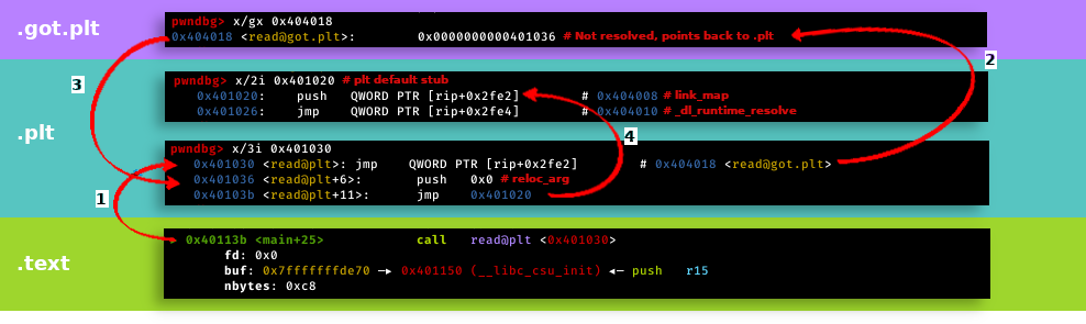
- from the text section, the plt function for read is called
- from the plt it is jumped to the got. if the symbol has already been resolved, a libc address would be in it.
- in this case, the symbol hasn’t been resolved and we jump back to the plt. some arguments for the linker are pushed onto the stack and the linker is called. it will resolve the function that we wanted to call earlier and jump to that function.
the Windows OS and kernel
overview
Windows originally was a GUI for MS-DOS. it was created in 1985. now it is arguably the most popular operating system. the standard file format for executables is PE.
the Windows kernel
the base principle of how the Windows kernel works is basically the same as the Linux kernel. the only difference is, that some device drivers or other kernel services can be in userspace too. that’s why the Windows kernel is a hybrid kernel (a mixture of monolithic (kernel services in kernel space) and microkernel (kernel services in user space)).
syscalls and interrupts
again, the base principle of syscalls and interrupts is the same. they are used to interface with the system. but in Windows, a userspace program will never use interrupts and syscalls directly. that’s because the syscall numbers change very often. on Linux, they don’t. because of this reason, you use a library called ntdll.dll. it is like the libc.so.6 in Linux. but you have to use the ntdll library every time you want to do low-level stuff. it handles the syscalls and calls them correctly.
modern exploit mitigation features (kernelspace)
| kernel access layout space randomization (kaslr) | supervisor mode execution protection (smep) | supervisor mode access prevention (smap) | kernel page table isolisation (kpti) | kernel data protection (kdp) |
|---|---|---|---|---|
| the kernel base address is randomized | marking non kernel space pages as nonexecutable | marking non kernel space pages as nonaccessible | separation of user and kernel land pages | marking critical kernel pages as readonly |
Windows calling convention
x86-64
| parameter type | arg1 | arg2 | arg3 | arg4 | arg5+ |
|---|---|---|---|---|---|
| float | xmm0 | xmm1 | xmm2 | xmm3 | [ebp+0x0] |
| non-float | rcx | rdx | r8 | r9 | [ebp+0x0] |
PE file format
overview
the PE file format is the standard executable file format on Windows. it is based on the COFF file format which was used earlier.
structure
here you can see the structure of a PE file
lower addresses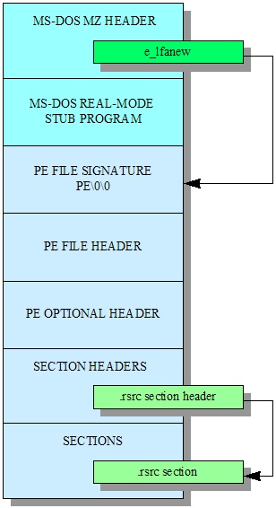
higher addresses
the DOS header is there for compatibility reasons. if we try to execute a PE from DOS on Windows, we get a notification that this application is for DOS. same the other way around. the MS-DOS real-mode stub program displays this message. the PE header contains information that concerns the entire file. it consists of basic information, like the PE magic. the optional PE header follows directly after the standard PE header. its size is specified in the PE header which you can also use to tell if the optional header exists. the magic code field can be used in conjunction with the machine type to see in the PE header to detect if the PE file is running on a compatible system. there are a few other useful memory-related variables including the size and virtual base of the code and data, as well as the application’s version number, entry point, and how many directories there are. a PE file is made up of sections which consist of a name, offset within the file, virtual address to copy to, as well as the size of the section in the file and in virtual memory (which may differ, in which case the difference should be cleared 0s), and associated flags. each section has an entry in the section header table.
modern exploit mitigation features
| access layout space randomization (aslr) | access layout space randomization for user binaries (like pie) | force aslr | stack canaries |
|---|---|---|---|
| randomization of shared library and stack addresses etc. | randomization of the programs base address | forced randomization of every programs base address | protection of buffer overflow |
sources
Picture 1: http://computerscience.gcse.guru/wp-content/uploads/2016/04/Von-Neumann-Architecture-Diagram.jpg Picture 2: https://upload.wikimedia.org/wikipedia/commons/thumb/d/dc/MMU_principle_updated.png/325px-MMU_principle_updated.png Picture 3: https://upload.wikimedia.org/wikipedia/commons/thumb/5/50/Program_memory_layout.pdf/page1-225px-Program_memory_layout.pdf.jpg Picture 4: https://www.researchgate.net/profile/Wai-Kyi/publication/334531571/figure/fig2/AS:781892970369029@1563429219773/Basic-architecture-of-ELF-file-format-16.ppm Picture 5: https://syst3mfailure.io/ret2dl_resolve/assets/images/lazy_binding.png Picture 6: https://wiki.osdev.org/images/d/dd/PEFigure1.jpg